Journal of Robotics, Automation and Smart Systems
ABSTRACT
Background
This study presents a comprehensive finite element analysis (FEA) of a biomimetic robotic finger to evaluate its structural and dynamic performance when fabricated from two distinct materials: an aluminum alloy and a carbon-fiber composite.
Methods
Static structural and Modal analysis was conducted using two flexion-based load cases representative of typical and high-grasp human finger postures.
Keywords : Robotic Finger; Finite Element Analysis; Composite Material; Structural Integrity; Modal Analysis; Lightweight Design
INTRODUCTION AND LITERATURE REVIEW
Biomimetics, practice of using building machines inspired from natural phenomena, biological systems and evolutionary principles. Human finger is one of the most optimized systems containing multiple degree of freedom, compliant grasp operations and finely distributed internal stress paths. Human finger is an engineering marvel that’s why engineers try to imitate it into robots as it provides great functionality. However, it is a complex engineering challenge to recreate human finger as a close knowledge of how the human hand operates assuming that all its parts (bones, tendons, ligaments, and soft tissues) interact in order to produce the fine motion and evocative interaction. The challenge to imitate such dexterity is quite an issue in engineering where the design panel would have to consider the joint kinematics, degree of freedom, material compliance, load bearing behavior and stability at different exerted forces [1,2]. Robotic fingers being designed currently provides good motion driven performance and efficient force transfer but extreme structural rigidity prevent fingers adapting to irregular objects due to limitation it lacks versatility in manipulation tasks [3].
In order to overcome current challenges of robotic finger researcher have carried out investigations with the hierarchical structure of the human finger, tendon-driven systems, compliant sections, flex-pathways of actuation, and thin layers of soft materials that can replicate the human force distribution and enable fingers to better deform into the surface of objects have been created [4,5]. This increase robotic finger adaptability but simultaneously introduces nonlinear deformation behavior, multifaceted material-structure interactions and changing stress pathway, which must be subjected to rigorous mechanical assessment to guarantee reliability and durability [6].
In light of these challenges for robotic finger biomimetic design structural analysis becomes critical. Robotic fingers functionality is dependent on structures external load handling resulting without failure. Finite element modeling of structures helps in evaluating stress strain response of structure based on material, geometry, loading and boundary conditions [7]. Robotic finger design evaluation based on structural mechanics principles is widely adopted by researchers. In prosthetics, bio-inspired designs improve comfort and reduce tissue stress by replicating natural load distribution [8]. Biomimetic load transfer is seen in rehabilitation exoskeletons to allow these robots to be safe, whereas nature-inspired geometries are used in industrial grippers to improve force distributions and minimize the wear that occurs when they come into contact [9]. Finite element analysis (FEA) tool is essential for structural evaluation of robotic fingers allowing designers to predict behavior of structure under operation scenarios before manufacturing.
Recent studies of robotic fingers are focused on merger of natural architectures with structural robust designs e.g. pneumatic actuators as a means to perform smooth deformation under load [10]. Detailed biomechanics of a human finger have been considered by others to provide stress-related information about artificial counterparts [11-13]. All these works together emphasize the necessity of having the balance between mobility, adaptability and structural robustness within the single system of biomimicry.
Considering the fast rate of biomimetic robotic fingers evolution, structural, kinematic, and material-based design strategies are necessary in order to state development of a reliable and high-performance robotic manipulation system. The evolution of the development of the biomimetic robotic fingertips has been driven by numerous themes starting with the earliest researches on the biomechanics of the human fingers and the current research on how tendons can contribute to developing more complex biomimetic robotic fingers through the development of soft composite and hybrid biomimetic robots. Both studies show the relevance of structural analysis in forecasting mechanical response, optimizing material behavior, and efficiency of design.
Material optimization strategies are also widely discussed in literature. Simone have given a dynamic FE model of a finger driven by Ni-Ti shape memory alloy (SMA) wires and confirmed its performance on various geometric and actuation factors [14]. Their findings highlight the nonlinear and hysteretic behavior of SMA materials and the need for accurate structural coupling in FE simulations. Similarly, Biswal analyzed a five-finger underactuated robotic hand through a finite element analysis to determine stress, strain, and pattern of deformations in various materials, and show a choice of possible candidate materials to use to construct a robotic finger [15]. Chen presented a pneumatic soft robotic hand in the wave shaped contours, which demonstrated consistent bending behavior and better grasping capability proven by both FE models and experimental work [16]. Safvati optimized a composite finger, made of Fin Ray, with reinforced geometries and demonstrated that the grip force, load distribution and structural reliability increased significantly, with a 63% better gripping entity compared to baseline designs [17].
Increasing operational demand for robotic fingers requires lightweight, structural and dynamic stability. In previous studies, metallic and composite materials have been used for robotic fingers for improved stiffness enhancement, actuation efficiency, and grasping performance. Major studies have focused on geometry, boundary conditions and actuation strategies not focusing on material comparison. Fewer studies have carried out combined modal and static analysis for robotic fingers, and material optimization studies are a rarity. The current study addresses this gap by a FEA-based comparison between aluminum alloy and carbon fiber composite under same boundary conditions, geometric features and loading scenarios. This study evaluates material selection effect on stress distribution, deformation, and dynamic characteristics. This study is positioned as a study diverging in the area of material selection effect of biomimetic finger response.
MATERIALS AND METHODS
In this study, static and modal (vibrational) analysis of a biomimetic robotic finger were used to assess the structural integrity. Ansys Mechanical software was used to carry out this study. This section outlines the methodology and methods used to carry out this study. The flow of subsections is as below: Mathematical modelling, CAD development, Material properties, meshing and interactions, load and boundary conditions.
Mathematical Modelling
The Finite Element Analysis (FEA) method was employed to simulate the static and modal response of the biomimetic robotic finger. The mathematical models used for analysis are based on the standard matrix form of equilibrium equations commonly used in structural mechanics.
Static Structural Analysis
Finite Element modelling is governed by Hook’s Law as shown below in Equation 1:
Ku=F (1)
In equation, K is the global stiffness matrix, u is the global displacement vector, and F is the external force acting on the respective nodal locations [18].
The element stiffness matrix is the cumulative of nodal stiffness obtained by Equation 2:
Where, B is strain–displacement matrix, D is the constitutive matrix, T is the thickness of the element, and V is element volume.
Modal (Free-Vibration) Analysis
The Modal (Free Vibration) analysis is based on the classical equation of motion for a free, undamped structural system Equation 3:
Where the sum of inertial forces (Mü) and elastic restoring forces (Ku) be zero as no external r damping force exists on system [19].
Assuming a harmonic motion u(t)=ϕe iωt leads to the standard eigenvalue problem as shown in Equation 4:
While, M is a global mass matrix, ϕ is the mode shape vector and d is the natural frequency.
CAD Modeling
A three-dimensional CAD model of a robotic finger was developed using SolidWorks, ensuring accurate representation of the finger’s anatomical structure.
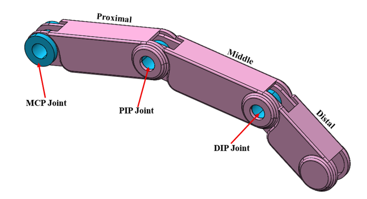
Figure 1: 3D CAD for biomimetic robotic finger
As shown in Figure 1 CAD model consisted of proximal, middle, and distal phalanges connected through joints depicting Metacarpophalangeal (MCP), Proximal Interphalangeal (PIP), and Distal Interphalangeal (DIP) joints as in a human finger. The robotic finger proportions and rotations were designed to mimic human finger motions during flexion, mimicking a human finger. The division of fingers into distinct sections enabled easier application of joint rotations and improved control over boundary conditions.
Material Properties
Material properties used for the analysis were sourced from the ANSYS Granta and supported by a review of existing literature on robotic hand structures and lightweight mechanisms [15]. Table 1 outlines the material properties used for the analysis of the robotic finger. The aluminum alloy offers excellent ductility, machinability, adequate stiffness, and high strength, making it suitable for components that require both formability and load-carrying capacity. The carbon-fiber composite, on the other hand, provides an exceptional strength-to-weight ratio and very high stiffness, making it ideal for lightweight yet structurally efficient designs.
It is acknowledged able that carbon fiber is anisotropic in reality, and isotropic modelling cannot capture the effect of directional stiffness, failure mechanisms, and interlaminar stresses of laminated composites. However, in present study carbon fiber was considered as an isotropic by using a first-order approximation for structural and model assessment rather than detailed composite failure prediction based on literature [15]. While, future studies will discuss detailed anisotropic behavior, layup orientation, and composite-specific failure.
|
Property |
Aluminum Alloy |
Carbon Fiber |
|
Density (kg/m³) |
2770 |
1800 |
|
Young’s Modulus (GPa) |
71 |
395 |
|
Poisson’s Ratio |
0.33 |
0.2 |
|
Shear Modulus (GPa) |
26.692 |
8 |
Table 1: Material properties utilized for analysis in ANSYS Workbench [15]
Meshing and Interactions
In order to validate the efficacy of the FEA results, a mesh sensitivity analysis was performed based on literature [20,21] guidelines and results are presented in Table 2. A global mesh size of 1mm was used, which provided a balance between computational efficiency and accuracy. To improve stress resolution near joints, a sphere. To increase stress resolution near joints by reducing the mesh size to 0.5 mm around PIP and DIP joint regions, as shown in Figure 2.
|
Mesh Size (mm) |
Stress (MPa) |
Frequency (Hz) |
||
|
Aluminum |
Carbon Fiber |
Aluminum |
Carbon Fiber |
|
|
2.5 |
0.95 |
5.38 |
65.32 |
100.38 |
|
2 |
1.24 |
6.54 |
67.25 |
103.55 |
|
1.5 |
1.47 |
7.32 |
68.99 |
104.53 |
|
1 |
1.55 |
8.64 |
69.11 |
106.14 |
|
0.5 |
1.59 |
8.98 |
69.75 |
106.98 |
Table 2: Mesh Convergence analysis for robotic finger
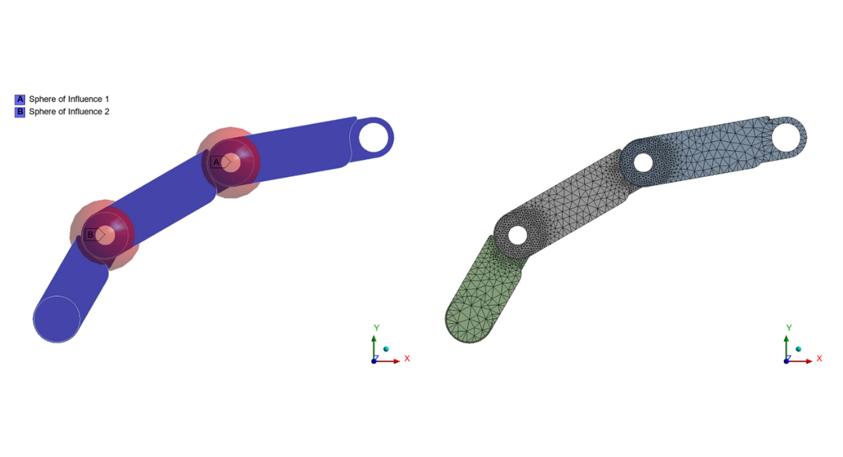
Figure 2: Meshing control applied for robotic finger
The contact interactions were defined as Frictionless between phalanx surfaces to replicate the natural sliding behavior found in finger joints, and PIP and DIP joints were modelled with rotational constraints allowing controlled rotations corresponding to selected load cases, as shown in Figure 3. MCP joint was fixed to the anchor finger.
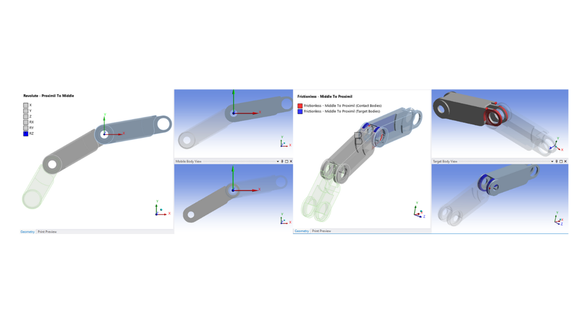
Figure 3: Implementation of frictionless contact and joint rotation to robotic finger
Load and Boundary Conditions
The load and boundary conditions for this study were selected based on a detailed review of biomechanical and robotic finger literature. Two flexion-based load cases are shown in Table 2. Each load case represents a different posture of the finger in a general use condition. Applying fingertip forces often results in convergence issues due to complex interactions, so joint rotations were used as the primary loading method. This approach is widely used in FEA studies of biological robotic joints due to the stable numerical performance, and it accurately encapsulates physiological finger movement. The first load case, LC 1 represents a moderate flexion of the finger where the PIP joint is rotated to 34° and the DIP to approximately 23°, maintaining a coupling ratio of 2:3. This configuration is consistent with the flexion posture reported by Peshin [22]. LC 2 load case represents a strong flexion during grasping motion in tendon-driven robotic fingers with PIP rotated to 60° and DIP between 40° and 45°, similar to flexion angles reported by Zhou [23]. Load cases LC 1 and LC 2 capture both typical and near maximum functional flexion, allowing assessment of stress and deformation characteristics encountered by robotic fingers for both Aluminum and carbon fiber designs.
|
Load Case |
PIP Rotation |
DIP Rotation |
Flexion Level |
Purpose |
|
LC 1 |
34° |
23° |
Moderate |
Evaluate stresses under typical-use conditions |
|
LC 2 |
60° |
45° |
High |
Represents a strong grasping posture |
Table 2: Load cases applied to the robotic finger for stress analysis [22,23]
The MCP joint was constrained in all degrees of freedom for all simulation cases, serving as the fixed support for both stress and modal analyses. This assumption is consistent with robotic finger studies, keeping the proximal end of the finger anchored to the base or mounting assembly. This methodological framework helps to evaluate the robotic fingers' structural and dynamic behavior with high fidelity comparison between metal and composite materials. The boundary condition pictorial representation is shown in Figure 4.
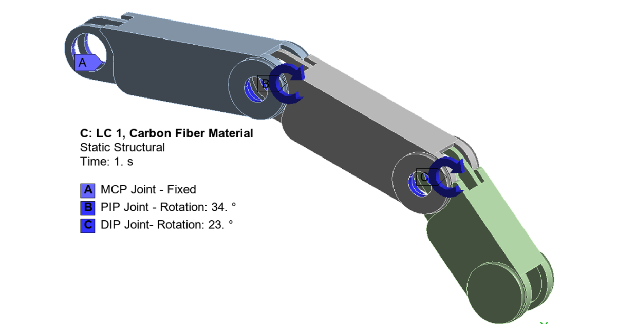
Figure 4: Load and boundary conditions implemented for robotic arm analysis
RESULTS AND DISCUSSIONS
Stress Analysis Results
A finite element–based static analysis was performed on the biomimetic robotic finger to evaluate its structural response under typical flexion movements. Two load cases (LC1 and LC2), representing common human finger-flexion conditions, were applied to assess the deformation and stress behavior of the finger during routine operation.
Figure 5 presents the deformation contours for both load cases. The maximum deflection recorded for LC1 was 39.03 mm, while LC2 produced a larger deflection of 55.50 mm. These deformation results effectively illustrate the finger’s bending behavior under natural operating conditions. Similar deformation patterns were observed for both material configurations due to identical geometry and the predominantly rotational nature of the applied loading. However, differences in equivalent stress values emerged as a consequence of the distinct material properties of the aluminum alloy and carbon-fiber composite.
Figure 6 shows the equivalent stress distribution for LC1. The aluminum-alloy finger exhibited a maximum equivalent stress of 1.55 MPa, whereas the carbon-fiber finger reached 8.61 MPa. This difference is expected, as aluminum’s higher shear modulus allows for lower stress values due to the greater shear modulus, while the brittle nature of carbon fiber results in higher localized stress concentrations.
Under LC2 loading (Figure 7), both materials experienced elevated equivalent stress levels due to the increased rotational load angle. The aluminum-alloy finger reached a peak stress of 2.13 MPa, while the carbon-fiber finger exhibited a higher value of 11.85 MPa. These results align with the higher bending and shear demands imposed by LC2 compared to LC1.
Figure 8 summarizes the stress–strain behavior of both materials under the two load cases. The aluminum finger required higher stress to achieve comparable deformation relative to the carbon-fiber finger. Although aluminum has a lower Young’s modulus, its higher shear modulus makes it better suited to withstand rotational and shear-dominant loading. Consequently, the aluminum-alloy configuration demonstrated superior performance under the applied flexion loads when compared to the carbon-fiber finger.
The stress magnitudes for both materials remain way below typical yield or failure thresholds reported in the literature. Stress contours show structural response under identical kinematic loading conditions and do not highlight imminent material failure. Analysis highlights that both materials possess sufficient rigidity required for flexion motions, which is dependent on strong stiffness, mass and dynamic performance rather than static strength.
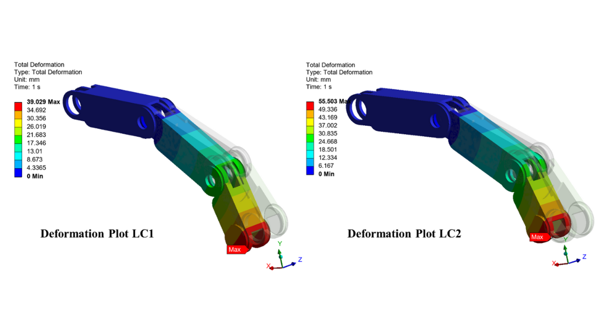
Figure 5: Deformation plot for robotic finger for LC1 and LC2
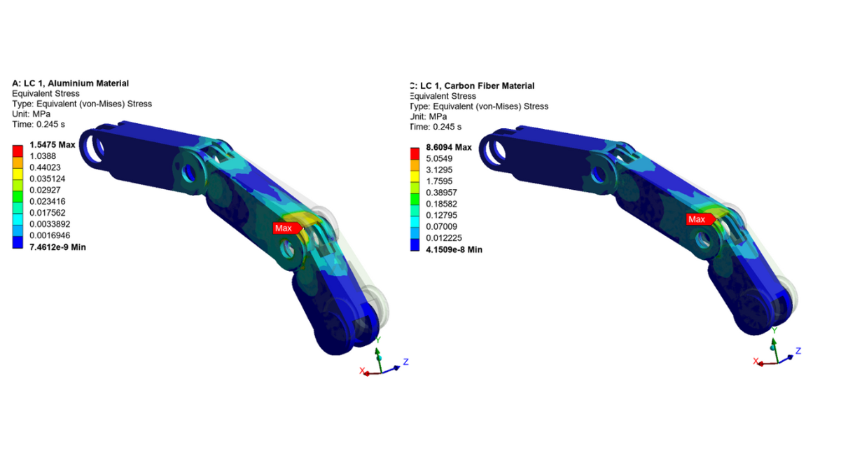
Figure 6: Equivalent Stress plots for LC 1
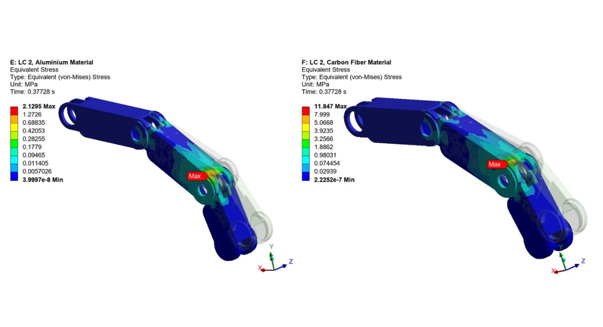
Figure 7: Equivalent Stress plots for LC 2
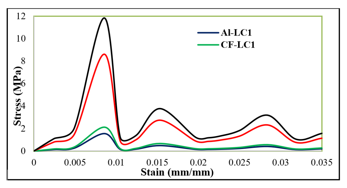
Figure 8: Stress strain for both composite and metal material
Modal Analysis
To evaluate the dynamic behavior of both the aluminum and carbon-fiber robotic fingers, a modal analysis was carried out to determine their natural frequencies and corresponding mode shapes. Understanding these dynamic characteristics is crucial, as the robotic finger must operate without encountering resonance, which could lead to amplified vibrations, reduced performance, or even structural failure. Figure 9 illustrates the mode shapes of the robotic finger. Mode 1 and Mode 2 correspond to low-frequency global deformation patterns typically bending for Mode 1 and twisting for Mode 2. The modal frequencies listed in Table 3 show that the aluminum finger exhibits natural frequencies of 69.11 Hz and 234.31 Hz for the first two modes, whereas the carbon-fiber finger shows frequencies of 106.14 Hz and 598.06 Hz. The higher modal frequencies of the carbon-fiber design indicate its greater stiffness and improved resistance to fundamental bending and twisting when compared with the aluminum finger. Higher-order mode shapes involve more complex vibration patterns, such as localized bending (Mode 3) or higher-order flexural deformation (Mode 4). For these modes, the aluminum finger has natural frequencies of 819.74 Hz and 3556.2 Hz, while the carbon-fiber finger reaches significantly higher values of 2398.5 Hz and 10,405 Hz. This order-of-magnitude increase from low-order to high-order modes is typical for slender structures such as a robotic finger. Overall, the carbon-fiber finger demonstrates substantially higher stiffness and superior dynamic performance, with natural frequencies between two and three times greater than those of the aluminum finger across all mode shapes and consistent with the recent literature study that demonstrate composite material shows 2 to three time higher frequency as compared to metal [24].
|
Mode |
Frequency (Hz) |
|
|
Aluminum |
Carbon Fiber |
|
|
1 |
69.11 |
106.14 |
|
2 |
234.31 |
598.06 |
|
3 |
819.74 |
2398.5 |
|
4 |
3556.2 |
10405 |
Table 3: Mode shapes result for the metal and composite robotic finger
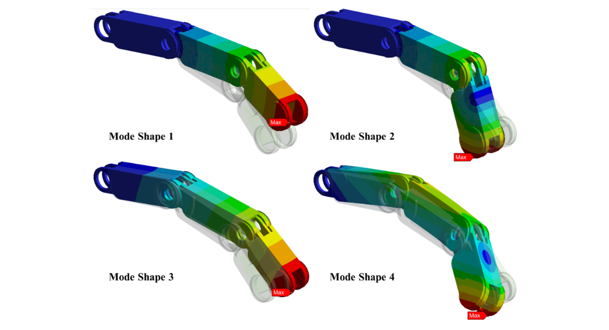
Figure 9: Mode shape contours for the robotic finger
Mass-Normalized Performance
Absolute stress and modal frequency comparisons, mass-normalized performance provides a comprehensive comparison of material selection in biomimetic fingers. Mass normalization of carbon fiber fingers with mass makes carbon fiber more pronounced. Although aluminum fingers show lower absolute stress contours when normalized to mass make it an inferior alternative. Carbon fiber finger achieves higher natural frequencies at lower mass, indicating enhanced dynamic efficiency per unit weight. Mass normalization analysis highlights the superior structural and dynamic performance of the composite finger with a bare minimum mass penalty. A quantitative mass normalized matrix is beyond the scope of this study, observed trends favor composite design when performance is evaluated relative to material density reinforcement suitability for high-speed and precise robotic, manipulation tasks.
The results showed that the aluminum finger experienced significantly lower equivalent stresses (1.55–2.13 MPa) compared to the carbon-fiber finger (8.61–11.85 MPa), indicating superior performance under static loading. However, modal analysis revealed that the carbon-fiber finger possessed substantially higher natural frequencies across all mode shapes, with increases of two to three times relative to the aluminum design. These elevated modal frequencies reflect greater structural stiffness and improved resistance to vibration and resonance
CONCLUSIONS AND FUTURE RECOMMENDATIONS
In this study, a biomimetic robotic finger was evaluated under two load cases representative of everyday human finger use. Finite Element (FE) analyses both static and dynamic were performed to determine which finger design provides superior performance under these conditions. In the static analysis, the aluminum-based finger demonstrated excellent structural behavior, with maximum stresses of 1.55 MPa and 2.13 MPa for Load Cases 1 and 2, respectively. In comparison, the carbon-fiber finger experienced higher stresses of 8.61 MPa and 11.85 MPa, approximately five times greater than those of the aluminum design. Mass normalization of stress results showed that the aluminum finger had a lower absolute stress value but when considering mass made carbon fiber composite finger was a more suitable solution. However, the dynamic analysis revealed an opposite trend. The carbon-fiber finger exhibited superior resistance to vibration, characterized by delayed low-mode and high-mode frequency responses (Mode 1: 106.14 Hz, Mode 2: 598.06 Hz). This indicates a stiffer dynamic behavior and an enhanced ability to withstand oscillatory loading.
In this study, a consistent numerical comparison of metallic and composite robotic finger designs was carried out to outline the impact of the material of structural stability of biomimetic fingers. Future studies will incorporate anisotropic composite modeling with explicit layup to influence effect of layup a fiber direction on stress distribution and dynamic response. Composite failure models, Tsai-Hill or Hashin, will be used to assess structural stability and mass normalization and energy-based indicators will be investigated to further quantify stiffness-to-weight advantages. Finally validating study with experimental testing of finger prototypes.
Overall, although aluminum offered better stress performance under static loading, the carbon-fiber finger demonstrated markedly superior dynamic behavior, making it a more suitable material choice for robotic fingers operating in environments where vibration stability and dynamic robustness are critical.
AUTHOR CONTRIBUTIONS
Conceptualization and methodology were developed by Ahmed Kadhim Zarzoor, Muhammad Mubashir and Muhammad Shoaib-Ur-Rehman. Finite element modeling and simulations were performed by Anas Asim, Rayyan Qaisar, and Ahmed Imtiaj. CAD modeling and material assignment were carried out by Sarfraz Shoukat and Naji Ullah. Result analysis and validation were supported by Abdul Ghaffar and Chaudhry Umer. Manuscript drafting and revision were completed collaboratively by all authors. All authors approved the final manuscript.
CONFLICT OF INTEREST
The authors declare no conflict of interest.
DATA AVAILABILITY STATEMENT
Data can be obtained from corresponding author upon reasonable request.
REFERENCES
- Howe RD, Cutkosky MR. Dynamic tactile sensing: Perception of fine surface features with stress rate sensing. IEEE transactions on robotics and automation. 2002;9(2):140-51. [Crossref] [Google Scholar]
- Santello M, Flanders M, Soechting JF. Postural hand synergies for tool use. Journal of neuroscience. 1998;18(23):10105-15. [Crossref] [Google Scholar] [PubMed]
- Bicchi A. Hands for dexterous manipulation and robust grasping: A difficult road toward simplicity. IEEE Transactions on robotics and automation. 2002;16(6):652-62. [Crossref] [Google Scholar]
- Dollar AM, Howe RD. The highly adaptive SDM hand: Design and performance evaluation. The international journal of robotics research. 2010;29(5):585-97. [Crossref] [Google Scholar]
- Majidi C. Soft robotics: a perspective—current trends and prospects for the future. Soft robotics. 2014;1(1):5-11. [Crossref] [Google Scholar]
- Hosoda K, Tada Y, Asada M. Anthropomorphic robotic soft fingertip with randomly distributed receptors. Robotics and Autonomous Systems. 2006;54(2):104-9. [Crossref] [Google Scholar]
- Odhner LU, Jentoft LP, Claffee MR, Corson N, Tenzer Y, et al. A compliant, underactuated hand for robust manipulation. The International Journal of Robotics Research. 2014;33(5):736-52. [Crossref] [Google Scholar]
- Jacobson SC, Knutti DF, Johnson RT, Sears HH. Development of the Utah artificial arm. IEEE Transactions on Biomedical Engineering. 1982;30(4):249-69. [Crossref] [Google Scholar] [PubMed]
- Kim S, Laschi C, Trimmer B. Soft robotics: a bioinspired evolution in robotics. Trends in biotechnology. 2013;31(5):287-94. [Crossref] [Google Scholar] [PubMed]
- Teeple CB, Becker KP, Wood RJ. Soft curvature and contact force sensors for deep-sea grasping via soft optical waveguides. In2018 IEEE/RSJ International Conference on Intelligent Robots and Systems (IROS) 2018 (pp. 1621-1627). IEEE. [Crossref] [Google Scholar]
- Shao F, Childs TH, Henson B. Developing an artificial fingertip with human friction properties. Tribology international. 2009;42(11-12):1575-81. [Crossref] [Google Scholar]
- F Avilés O, H Sánchez D, Rivera O, F Mauledoux M, Caldas O. Biomechanical Considerations in the Design of an Artificial Hand. International Journal of Mechanical Engineering and Technology. 2019;10(12). [Google Scholar]
- Butz KD, Merrell G, Nauman A biomechanical analysis of finger joint forces and stresses developed during common daily activities. Computer methods in biomechanics and biomedical engineering. 2012;15(2):131-40. [Crossref] [Google Scholar] [PubMed]
- Simone F, Meli D, Rizzello G, Naso D, Seelecke S. Finite element modeling and simulation of a robotic finger actuated by Ni-Ti shape memory alloy wires. InBehavior and Mechanics of Multifunctional Materials XIII 2019 (Vol. 10968, pp. 98-107). SPIE. [Crossref] [Google Scholar]
- Biswal DR, Parida PK. Modelling and finite element based analysis of a five fingered underactuated robotic hand. International Journal for Research in Applied Science & Engineering Technology.;10(9):100-8. [Crossref] [Google Scholar]
- Chen H, Ali MA, Wang Z, Chen J, Ramadan MN, et al. Performance optimizing of pneumatic soft robotic hands using wave-shaped contour actuator. Results in Engineering. 2025;25:103456. [Crossref] [Google Scholar]
- Safvati M, Çetin N. Design of a reinforced composite robotic finger for enhanced soft grasping using the Fin Ray effect and FEM. CIRP Journal of Manufacturing Science and Technology. 2025;61:201-10. [Crossref] [Google Scholar]
- Moaveni S. Finite element analysis theory and application with ANSYS, 3/e. Pearson Education India; 2011. [Google Scholar]
- Krodkiewski JM. Mechanical vibration. The University of Melbourne–Department of Mechanical and Manufacturing Engineering. 2008. [Google Scholar]
- Mubashir M, Zarzoor AK, Asim A, Shoaib-Ur-Rehman M. A systematic framework for the design and material selection of composite for tennis racket upon impact. Discover Materials. 2024 ;4(1):57. [Crossref] [Google Scholar]
- Mubashir M, Zarzoor AK, Asim A, Akhter M, Shoaib-Ur-Rehman M, et al. Multi-objective optimization of aircraft wing design: integrating material selection, structural analysis, and topology optimization. International Journal on Interactive Design and Manufacturing (IJIDeM). 2025:1-7. [Crossref] [Google Scholar]
- Peshin S, Karakulova Y, Kuchumov AG. Finite element modeling of the fingers and wrist flexion/extension effect on median nerve compression. Applied Sciences. 2023;13(2):1219. [Crossref] [Google Scholar]
- Zhou X, Fu H, Shentu B, Wang W, Cai S, Bao G. Design and control of a tendon-driven robotic finger based on grasping task analysis. Biomimetics. 2024;9(6):370. [Crossref] [Google Scholar] [PubMed]
- Mubashir M, Shoukat S, Asim A, Zarzoor AK, Qaisar R, et al. Comparative Modal Analysis of Metallic and Composite Beam Configurations for Aerospace Structural Applications. Climate-Adaptive Materials Engineering. 2025 Dec 11;1(1):65-76. [Crossref] [Google Scholar]
Article Processing Timeline
| 2-5 Days | Initial Quality & Plagiarism Check |
| 25-35 Days |
Peer Review Feedback |
| 45-60 Days | Total article processing time |
Journal Flyer